Memory Virtualization in Operation Systems
Sources:
- Remzi H. Arpaci-Dusseau & Andrea C. Arpaci-Dusseau. (2014). Virtualization. Operating Systems: Three Easy Pieces (Version 0.8.). Arpaci-Dusseau Books, Inc..
Memory Virtualization
计算机的physical memory可以被虚拟化virtual memory. 由硬件MMU( Memory Management Unit ) 和 OS 共同实现.
虚拟化后, physical address space(PAS)被映射为virtual address space (VAS). 程序使用的只是virtual address, 在底层由MMU和OS将其转换为physical address, 即需要address translation:
\[ \operatorname{MAP}: \mathrm{VAS} → \mathrm{PAS} \cup \emptyset \] where $$ \[\begin{equation} \operatorname{MAP}(A)= \left\{ \begin{array}{lr} A^{\prime},\text{if data at virtual addr. A are present at physical addr. A′ in PAS} \\ \emptyset, \text{if data at virtual addr. A are not present in physical memory} \end{array} \right. \end{equation}\] $$
- 程序使用的只是virtual address, 因此我们常说的Address space 是VAS
- 一个使用VAS的例子是: 我们编写和编译程序时假定内存从0开始
Address Space
Address Space of Linux process
ld,ls等命令实际上会调用execve( /usr/bin/COMMAND )execve()只接受绝对路径
进程的地址空间 == 内存中若干连续的“段”
mmap可以将内存中的某一段映射到文件中的某一段进程中的代码和数据是
mmap从内存中映射的可以接受文件描述符
1
2
void *mmap(void *addr, size_t len, int prot, int flags,
int fildes, off_t off);
查看进程的地址空间:
pmap- 动态链接的程序比静态链接的小,并且链接得快, 用
pmap分别查看其内容:- 静态链接程序的地址空间中有其链接库的内容(二进制文件的代码、数据、bss等)
- 动态链接程序的地址空间中只有其链接库的指针
- 可以看到地址空间的高位有三个段:
vvar,vdso,vsyscall,用于virtual system callvirtual system call: 不陷入内核的系统调用
pmap实际上打印了/proc/PID/maps的一部分信息- 通过
strace pmap XX可以看到pmap调用了openat( XX, \proc\PID\maps )
- 通过
- 动态链接的程序比静态链接的小,并且链接得快, 用
Segmantation
在MMU中引入不止一个基址/界限寄存器对,而是给每个逻辑段一对,这可以将每个段独立地载入物理内存。 由于只有已用的内存才在物理内存中分配空间,因此可以容纳巨大的地址空间
- 段:在内存空间中的一段连续定长(段有段界限)区域
- 引用非法地址就会引发段错误
- 分段会造成外部碎片
We will use top few bits to indicate the segment number and the left bits for offset.

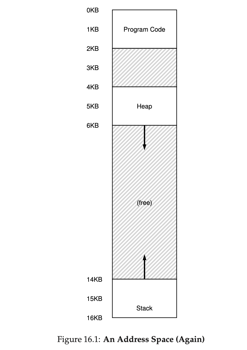
Let’s look at an example. Here we have an address space segmented into 3 segments: code, stack and heap:
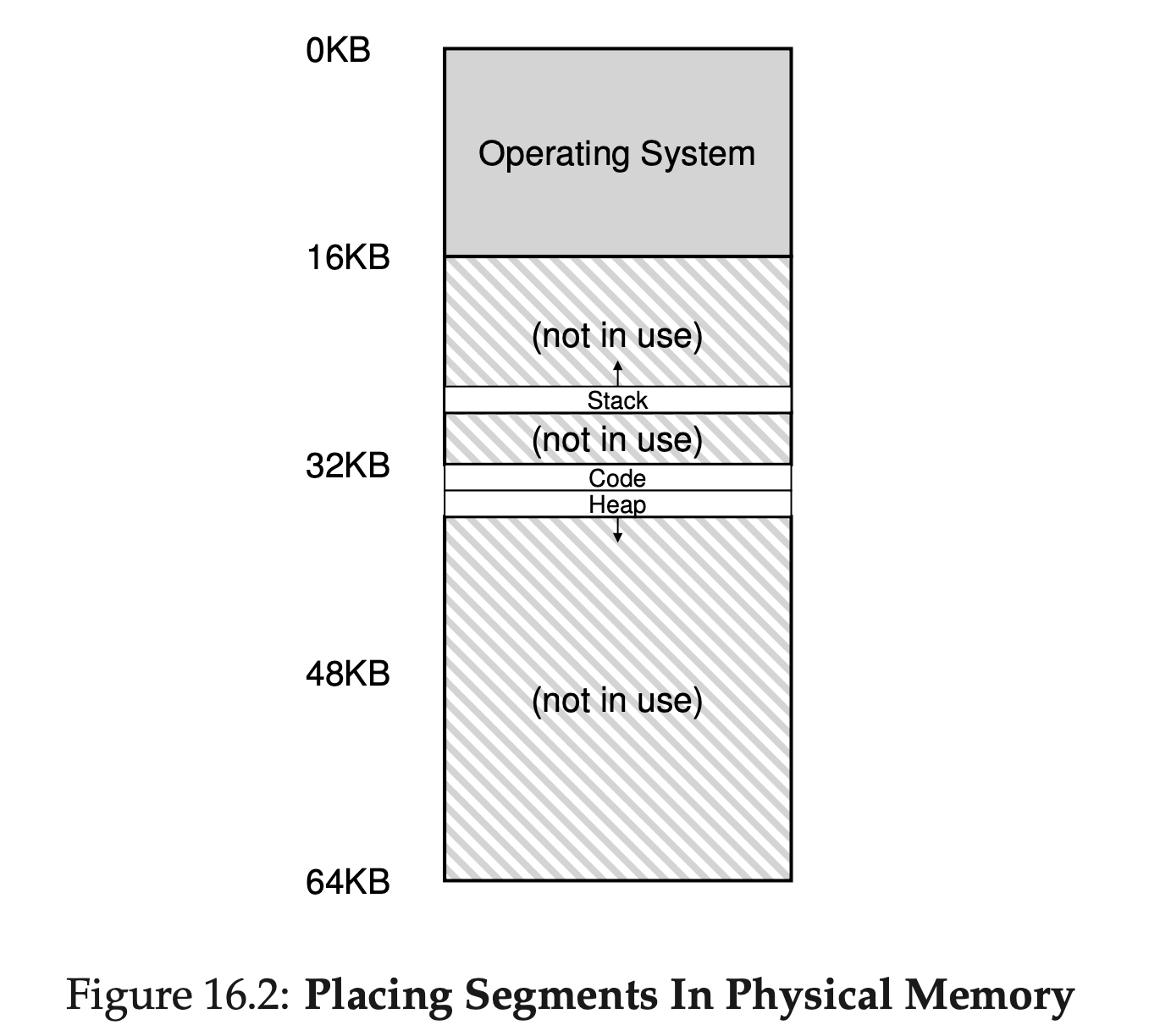
With a base and bounds pair per segment, we can place each segment independently in physical memory. For example, see Figure 16.2; there you see a 64-KB physical memory with those three segments within it (and 16KB reserved for the OS).
The hardware structure in our MMU required to support segmenta- tion is just what you’d expect: in this case, a set of three base and bounds register pairs.
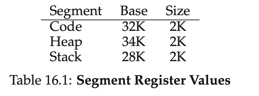
- Assume a reference is made to virtual address 100 (which is in the code segment), MMU will add the base value to the offset into this segment (100 in this case) to arrive at the desired physical address: 100 + 32KB, or 32868.
- It will then check that the address is within bounds (100 is less than 2KB), find that it is, and issue the reference to physical memory address 32868.
MMU needs to the the direction of growth of the segments. Because some segment, like stack, grows backwards – in physical memory, it starts at 28KB and grows back to 26KB, corresponding to virtual addresses 16KB to 14KB.

1 | # 段号掩码,二进制11刚好过滤出前两位段号 |
In reality, the segmentation is usually used in conjunction with pageing. So the address got from segmentation is usually the virtual address, instead of the physical address. The virtual address is then translated by paging to get the physical address.
Sharing
可以增加几位保护位,来表示段的权限,比如可以将代码段标记为只读, 同样的代码就可以被多个进程共享
Free space management
Since segmentation will chop the memory into variable-sized units, it results in the external fragmentation problem.

The figure shows an example of this problem. In this case, the total free space available is 20 bytes; unfortunately, it is fragmented into two chunks of size 10 each. As a result, a request for 15 bytes will fail even though there are 20 bytes free.
To solve this, we need some free-space management algorithm to manage the memory.
Assumptions
- 这里我们只讨论解决外部碎片(即分段)的空闲空间管理算法,假定算法管理的是一块块连续的字节区域(即内存块)
- 这里只考虑堆中的内存分配,即
malloc,free操作
Free list
1 | typedef struct node_t |
空闲列表就是一个链表,每个节点都记录了一块没有被分配的空间,假设有下面的 30 字节的堆:
A free list is a linked list where each element describes an unallocated free space. Thus, assume the following 30-byte heap:

The free list for this heap would have two elements on it. One entry de- scribes the first 10-byte free segment (bytes 0-9), and one entry describes the other free segment (bytes 20-29):

As described above, a request for anything greater than 10 bytes will fail (returning NULL); there just isn’t a single contiguous chunk of mem- ory of that size available. A request for exactly that size (10 bytes) could be satisfied easily by either of the free chunks. But what happens if the request is for something smaller than 10 bytes?
Assume we have a request for just a single byte of memory. In this case, the allocator will perform an action known as splitting: it will find a free chunk of memory that can satisfy the request and split it into two. The first chunk it will return to the caller; the second chunk will remain on the list. Thus, in our example above, if a request for 1 byte were made, and the allocator decided to use the second of the two elements on the list to satisfy the request, the call to malloc() would return 20 (the address of the 1-byte allocated region) and the list would end up looking like this:

A corollary mechanism found in many allocators is known as coalesc- ing of free space. Take our example from above once more (free 10 bytes, used 10 bytes, and another free 10 bytes).
Given this (tiny) heap, what happens when an application calls free(10), thus returning the space in the middle of the heap? If we simply add this free space back into our list without too much thinking, we might end up with a list that looks like this:

Note the problem: while the entire heap is now free, it is seemingly divided into three chunks of 10 bytes each. Thus, if a user requests 20 bytes, a simple list traversal will not find such a free chunk, and return failure.
What allocators do in order to avoid this problem is coalesce free space when a chunk of memory is freed. The idea is simple: when returning a free chunk in memory, look carefully at the addresses of the chunk you are returning as well as the nearby chunks of free space; if the newly- freed space sits right next to one (or two, as in this example) existing free chunks, merge them into a single larger free chunk. Thus, with coalesc- ing, our final list should look like this:

Indeed, this is what the heap list looked like at first, before any allo- cations were made. With coalescing, an allocator can better ensure that large free extents are available for the application.
头块
头块:
1 | typedef struct header_t{ |
free(void* ptr)函数没有指定块大小的参数,因为它假定,对于给定的指针,内存分配库可以确定要释放空间的大小,从而将其放回free list
一般这通过分配头块来实现。 每次分配内存块时,在其前面分配一个头块,保存额外信息,这样在(通过指针,也就是内存块起始位置)释放该内存块的时候,通过查询指针前面的头块,就知道了内存块的信息,比如大小,然后根据这些信息来释放内存块(头块也顺便被释放)
- 当然,这意味着malloc/free时,分配/释放的的内存大小,是想要分配/释放给用户的内存大小 + 头块大小
整体逻辑如下(假定内存从低位向高位分配,所以头块在内存块的前面):
1
2
3
4
5
6
7
8
9
10void free(void *ptr)
{
header_t *header_ptr = (void*)ptr - sizeof(header_t); // 根据分配给用户的内存指针,减去头块大小,获得头块的指针
//读取头块的信息
//...
//释放头块和内存块
//...
}
头块 + 空闲列表的实现
假定要管理4KB的内存块,它是个堆,先初始化堆,加入空闲列表的头节点(free list的节点大小是8B):
1 | node_t *head = mmap( NULL, 4096, PRPT_READ | PROT_WRITE, MAP_ANON | MAP_PRIVATE, -1, 0 ); |
- 执行这段代码之后,free list的状态只有一个节点,记录的空闲大小为 4088(因为已经分配了一个free list的节点,占了8B)
- head 指针指向这块区域的起始地址, 假设位于16KB(尽管任何虚拟地址都可以)。堆看起来如图 17.3 所示
- 假设有一个 100 字节的内存请求。为了满足这个请求,库首先要找到一个足够大小的块。因为目前只有一个 4088 字节的块,所以选中这个块。然后,这个块被分割(split) 为两块:一块足够满足请求(以及头块,如前所述),一块是剩余的空闲块。假设记录头块为 8 个字节(一个整数记录大小,一个整数记录幻数),堆中的空间如图 17.4 所示

至此,对于 100 字节的请求,库从原有的一个空闲块中分配了 108 字节,返回指向它的一个指针(在上图中用 ptr 表示),并在其之前连续的 8 字节中记录头块信息,供未来的 free()函数使用。同时将列表中的空闲节点缩小为 3980 字节(4088−108)。
之后的内存分配以此类推
如果用户程序通过 free(ptr)归还一些内存,那无非是让head指向ptr - 8,读取8字节的头块,得到要释放的内存信息,然后释放头块+紧跟的内存块:

- 这个堆的起始地址是16KB
- 假设要
free(16500)( 即16384( 16KB ) + 前一块的108 ),也就是图上的sptr指针, 则令head指向sptr前的头块,得到sptr(开头的)内存块的信息,然后删除头块和sptr内存块
Paging: Introduction
Paging is another way to virtualize memory. Instead of splitting up our address space into three logical segments (each of variable size), we
- split up our address space into fixed-sized units we call a page, and
- split physical memory into pages (with the same size) as well; we sometimes will call each page of physical memory a page frame.
Each page has a number, called virtual page number (VPN); each frame also has a number, called physical frame number (PFN).
With paging, we have two types of address:
- Virtual address := VPN + offset in the page.
- Physical address := PFN + offset in the frame.
We regulate that offset in the page == offset in the frame. Therefore, we only translate VPN to PFN. The address translation is done by a per-process data structure, called page table, by the operating system. The page table itself is stored in memory.
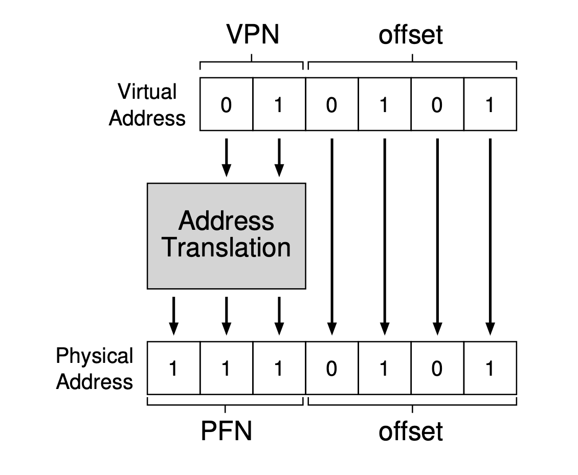
Simple example
Here in Figure 18.1 an example of a tiny address space, only 64 bytes total in size, with 16 byte pages (real address spaces are much bigger, of course, commonly 32 bits and thus 4-GB of address space, or even 64 bits). We’ll use tiny examples to make them easier to digest (at first).
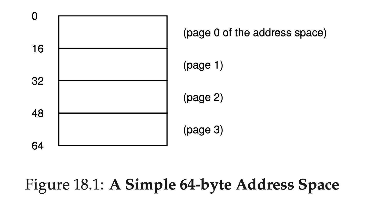
Thus, we have an address space that is split into four pages (0 through 3). With paging, physical memory is also split into some number of pages as well; we sometimes will call each page of physical memory a page frame. For an example, let’s examine Figure 18.2.
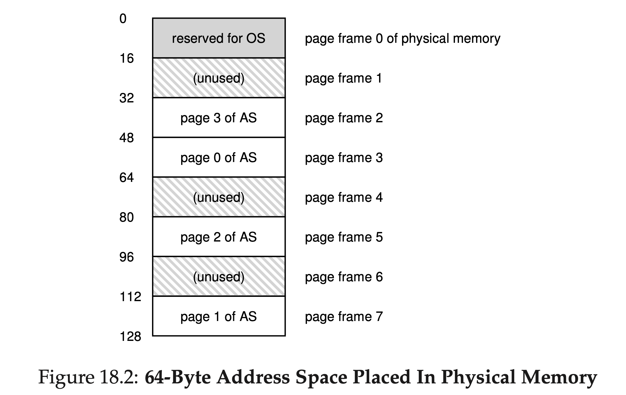
In this senario, the page table would thus have the following entries:
- (Virtual Page 0 → Physical Frame 3),
- (VP 1 → PF 7),
- (VP 2 → PF 5), and
- (VP 3 → PF 2).
Contents of a page table
Eacn page table entry (PTE) in the page table stores the PFN plus any other useful stuff.
Note: VPN is the index of the PTE. So VPN is not stored in the PTE.
"Useful stuff" includes:
- A valid bit to indicate whether the particular translation is valid, i.e., whether it can be used by the process.
- Some protection bits, indicating whether the page could be read from, written to, or executed from.

Figure 18.5 shows an example page table entry from the x86 architec- ture [I09]. It contains
- a present bit (P);
- a read/write bit (R/W) which determines if writes are allowed to this page; a user/supervisor bit (U/S) which determines if user-mode processes can access the page;
- a few bits (PWT, PCD, PAT, and G) that determine how hardware caching works for these pages;
- an accessed bit (A) and
- a dirty bit (D); and finally, the page frame number (PFN) itself.
页表基址寄存器( PTBR, page table base register ): 存储了页表的起始位置的物理地址,用于访问PTE:
1 | // 得到VPN |
只要查询页表,找到PTE(VPN就是PTE的下标),读取PTE,将VPN转换为PFN,再加上业内偏移,就得到了物理地址:
1 | offset = VirtualAddress & OFFSET_MASK PhysAddr = (PFN << SHIFT) | offset |
Address Translation
我们以分页作为虚拟化手段, 解释地址转换的过程:

Process
Page Hit
如果Page hit, 即PTE正确地存在页表中, 则:
- CPU生成一个virtual address, 送给MMU处理
- MMU根据VPN, 从cache/main memory中查找PTE
- The cache/main memory returns the PTE to the MMU.
- MMU根据PTE的内容(VPN - PFN的mapping), 组合出physical address, 然后送给cache/main memory.
- The cache/main memory returns the requested data word to the processor.

此时Address Translation是纯硬件的(CPU, MMU).
Page Fault
如果发生了page fault( MMU发现PTE的valid bit为false ), 则会由硬件和OS(负责中断)共同处理:

1~3. 和之前的步骤1~3一样,
- MMU发现PTE是invalid的, so the MMU triggers an exception, which transfers control in the CPU to a page fault exception handler in the operating system kernel.
- The fault handler identifies a victim page in physical memory, and if that page has been modified, pages it out to disk.
- The fault handler pages in the new page and updates the PTE in memory.
- 和其他异常中断一样, the fault handler返回原进程, CPU replay那条之前引起page fault的指令, 将virtual address再次送给MMU, 但由于此时的PTE已经存储在页表中了, 因此这是个page hit. 之后的过程就如之前page hit的情况
Integrating Caches and VM
采用虚拟化后, 指令执行就多了一次VA -> PA的映射, 对于分页来说, 也就是查询页表. 为了提高效率, 考虑到内存访问的Locality, 我们采用Cache的思想, 把常用的PTE存入一个Cache, 不需要每次都查页表了.
The main idea is that the address translation occurs before the cache lookup.
- Cache属于内存系统一部分, 面对的是Physical Address, cache对于物理地址是透明的.

Paging: Faster Translations (TLBs)
Using paging as the core mechanism to support virtual memory can lead to high performance overheads. To speed up address translation, we add a translation-lookaside buffer, or TLB to our system.
A TLB is part of the chip’s memory-management unit (MMU), and is simply a hardware cache of popular virtual-to-physical address translations; thus, a better name would be an address-translation cache.
TLB Basic Algorithm
TLB Organization
TLB一般是set associative cache(详见Cache Memory). 在TLB视角下, virtual address被划分如下:

- 注意: 和main memory cache不同, TLB划分的是虚拟地址, 而不是物理地址
- 在TLB视角下, VPN部分的高位存储tag, 低位存储set index; VPO部分似乎没有用???
- TLB是set associative cache, TLBE(TLB Entry)作为cache line, 里面也不会存储组号. 由于TLBE一般也不会存储标志位, 因此TLBE大小 = Tag大小 + PTE大小
- TLB 即为快表,快表只是慢表(Page)的小小副本,因此 TLB 命中,必然 Page 也命中,而当 Page 命中,TLB 则未必命中.
Address Translation Using TLB
使用TLB后, Address Translation过程如下:
对每次内存访问,OS先查看TLB,看是否有期望的转换映射.
有的话(TLB hit)就直接得到了PFN,不需要查页表. 没有的话( TLB miss )就继续查页表,
- 如果PTE Valid, 则进入步骤3.
- 如果PTE Invalid, 则从外部存储中得到PTE, 更新页表, 再重试查TLB的指令, 接着TLB会继续miss, 但查页表时会得到PTE Valid, 进入步骤3.
- 更新TLB, 并得到PFN, 拼接出PA.
- 可以看到, TLB 要么hit, 要么会有连续两次miss被年过半百
用PA来进行后续的内存访问( main memory cache, main memory, disk ...)

1 | VPN = (VirtualAddress & VPN_MASK) >> SHIFT |
TLB Hit

TLB Miss

Memory Access Using TLB
采用TLB后, 完整的内存访问过程如下:

TLB Refresh
- TLB存放了PTE集合,PTE只对页表有效,页表只对所属的进程有效,因此TLB只对所属进程有效. context switch时,要刷新TLB
- 刷新TLB会导致每次上下文切换后,都会有大量TLB miss, 为此,TLB实际上会存储多个进程(即多个页表)的PTE,并增加一个地址空间标识符字段(相当于PID),不同进程的PTE就用地址空间标识符来区分
- 除此之外,TLB项还有一些其他的控制位,比如有效位
- TLB的有效位和页表的有效位不同,如果PTE无效,表面该页没有被进程申请使用,访问该页是非法的;而TLB项无效,仅仅表明该TLB项不是有效的地址映射
TLB contents
TLB Issue: Context Switches
Paging: Smaller Tables
Hybrid Approach: Paging and Segments
Instead of having a single page table for the entire address space of the process, why not have one per logical segment? In this example, we might thus have
Hybrid approach: we can have one page table per segment! Thus, we will have three page tables, one for the code, heap, and stack parts of the address space.
The base register of each segment now points to the physical address of the page table of that segment.
Let’s do a simple example to clarify. Assume a 32-bit virtual address space with 4KB pages, and an address space split into four segments. We’ll only use three segments for this example: one for code, one for heap, and one for stack.
To determine which segment an address refers to, we’ll use the top two bits of the address space. Let’s assume 00 is the unused segment, with 01 for code, 10 for the heap, and 11 for the stack. Thus, a virtual address looks like this:

In the hardware, assume that there are thus three base/bounds pairs, one each for code, heap, and stack. When a process is running, the base register for each of these segments contains the physical address of a lin- ear page table for that segment.
Thus, each process in the system now has three page tables associated with it. On a context switch, these registers must be changed to reflect the location of the page tables of the newly-running process.
On a TLB miss (assuming a hardware-managed TLB, i.e., where the hardware is responsible for handling TLB misses), the hardware uses the segment bits (SN) to determine which base and bounds pair to use. The hardware then takes the physical address therein and combines it with the VPN as follows to form the address of the page table entry (PTE):
1 | SN = (VirtualAddress & SEG_MASK) >> SN_SHIFT |
Multi-level page tables
The page table itself is stored in the memory, i.e., it is saved in one physical frame. So what if the page table is too big that a single frame can't store it?
The solution is using a multi-level page table. Here we illustrate the idea of a 2-level page table.
We have a Outer Page Table (usually called page directory), whose each item (called page directory entriey, PDE) minimally has a valid bit and a page frame number (PFN). A PDE itself is a PTE since a page directory itself is a page table. The PFN points to the frame that contains an Inner Page Table.
1 | Physical Address Space = 2(44) B |
We can see that Page Table 1 is larger than 4KB (Frame size). Thus, this Page Table has to split into "sub page tables", each sub table is stored in a frame.
We have
1 | No. of pages of Page Table 2 (Outer Page Table) = (2(20) * 2(2)B) / 2(12)B = 2(10) pages |
So, the size of the Outer Page Table
1 | = 2(10) * 4B = 4KB |
The Outer Page Table can be stored in a frame as well.
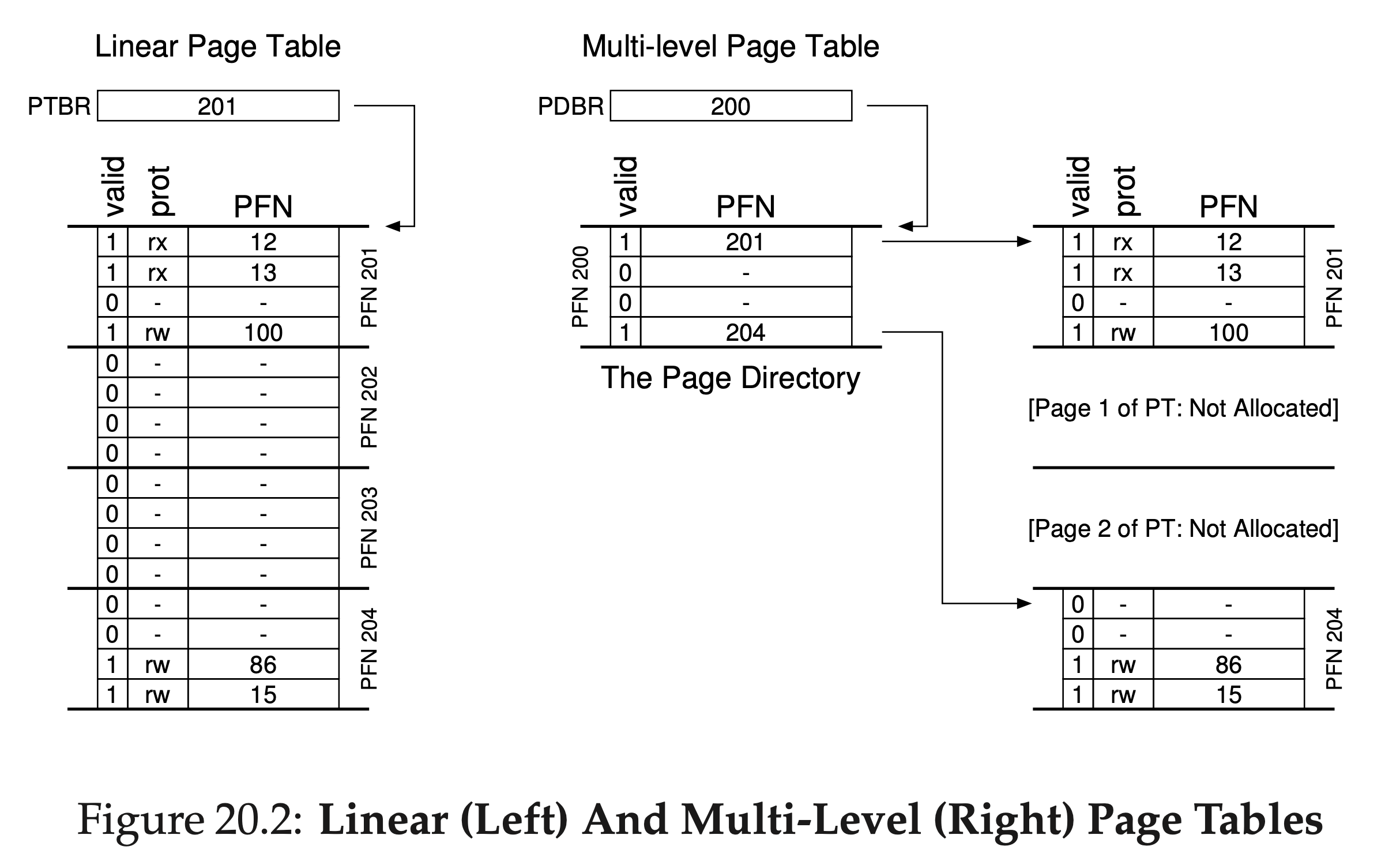
Another advantage of multi-level page table is that it can avoid allocating PTEs for invalid memory. Because if an entire page of page-table entries (PTEs) is invalid, we don’t allocate that page of the page table at all.
Figure 20.2 shows an example. On the left of the figure is the classic linear page table; even though most of the middle regions of the address space are not valid, we still have to have page-table space allocated for those regions (i.e., the middle two pages of the page table). On the right is a multi-level page table. The page directory marks just two pages of the page table as valid (the first and last); thus, just those two pages of the page table reside in memory. And thus you can see one way to visualize what a multi-level table is doing: it just makes parts of the linear page table disappear (freeing those frames for other uses), and tracks which pages of the page table are allocated with the page directory.
Example
To understand the idea behind multi-level page tables better, let’s do an example. Imagine that we have:
- a 16 KB address space (14-bit virtual address space)
- 8 bits for the VPN and 6 bits for the offset.
With A linear page table would have 2^8 (256) entries, even if only a small portion of the address space is in use. Here is an example:
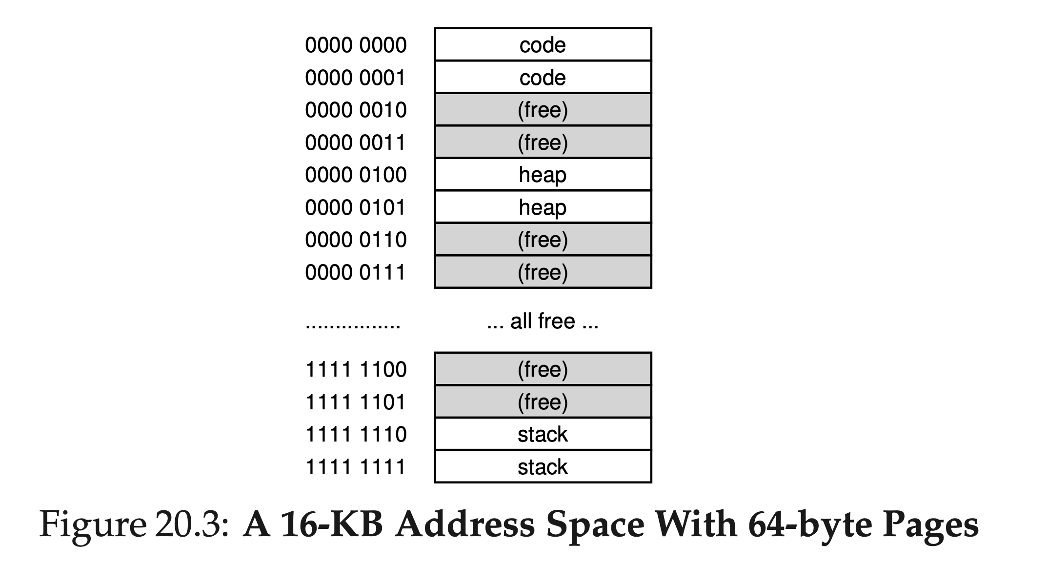
In this example,
- virtual pages 0 and 1 are for code,
- virtual pages 4 and 5 for the heap, and
- virtual pages 254 and 255 for the stack;
- the rest of the pages of the address space are unused.
To build a two-level page table for this address space, we start with our full linear page table and break it up into page-sized units. Recall our full table (in this example) has 256 entries; assume each PTE is 4 bytes in size. Thus, our page table is 1KB (256 × 4 bytes) in size. Given that we have 64-byte pages, the 1-KB page table can be divided into 16 64-byte pages; each page can hold 16 PTEs.
What we need to understand now is how to take a VPN and use it to index first into the page directory and then into the page of the page table. Remember that each is an array of entries; thus, all we need to figure out is how to construct the index for each from pieces of the VPN.
Let’s first index into the page directory. Our page table in this example is small: 256 entries, spread across 16 pages. The page directory needs one entry per page of the page table; thus, it has 16 entries. As a result, we need four bits of the VPN to index into the directory; we use the top four bits of the VPN, as follows:

Once we extract the page-directory index (PDIndex for short) from the VPN, we can use it to find the address of the page-directory entry (PDE) with a simple calculation:
1 | PDEAddr = PageDirBase + (PDIndex * sizeof(PDE)). |
If the page-directory entry is marked invalid, we know that the access is invalid, and thus raise an exception.
If, however, the PDE is valid, we have more work to do. Specifically, we now have to use this PTE to find the (inner) page table it pointing to. We now index into the portion of the page table using the remaining bits of the VPN:

This page-table index (PTIndex for short) can then be used to index into the page table itself, giving us the address of our PTE:
1 | PTEAddr = (PDE.PFN << SHIFT) + (PTIndex * sizeof(PTE)) |
Note that the page-frame number (PFN) obtained from the page-directory entry must be left-shifted into place before combining it with the page table index to form the address of the PTE.
Question
The following table shows a map of a subset of memory. Since I can't show you all 4GiB of memory, I have shown a few addresses and the 4 bytes stored starting at that address.
Some information about this system:
- The page size is 64KiB
- The physical address size is 32 bits
- The virtual address size is 26 bits
- There is a two level page table (each level is the same width)
- All PTEs are 32 bits.
- The internal PTEs only contains the address for the next level
- The leaf PTEs only contain the PPN, not the full address
| Physical address | 4 bytes of data |
|---|---|
0xf10de304 |
0x0cfa18b0 |
0xd6051c2c |
0xc0bf6c00 |
0xd6051c24 |
0x8dc35c00 |
0xd6051c10 |
0x93f04c00 |
0xd6051c00 |
0x74820c00 |
0xc0bfcf8c |
0xba03164c |
0xc0bf6c6c |
0x000034da |
0xb10a846c |
0x00003736 |
0xb10a10a4 |
0x62f4a7f8 |
0x93f04c5c |
0x000015c8 |
0x93f030ac |
0xf726b0e8 |
0x8dc35c00 |
0x00000784 |
0x8dc2ebc8 |
0x151764a4 |
0x8948e304 |
0x2a0cb1f0 |
0x74820c34 |
0x00003375 |
0x74818ddc |
0x137404f8 |
0x3736e304 |
0xf2137438 |
0x34dae304 |
0x3e751b14 |
0x3375e304 |
0x3f927b80 |
0x2efce304 |
0xa2913c34 |
0x15c8e304 |
0x974b8f44 |
0x0b5de304 |
0x299e04d0 |
0x0784e304 |
0xbdab3020 |
The base of the page table (e.g., satp or CR3 register) points to 0xd6051c00
Given this information, what data is returned when executing the following load?
1 | ld x4, 0(x1) |
Assume the effective address is 0x0120e304
Give your answer in hex (e.g,. 0xabcd): 0xbdab3020.
Solution:
First, the effective address in binary is:
1 | 0000 0001 0010 0000 1110 0011 0000 0100 |
This is a 32-bit physical address, we use the least 26 bits as the virtual address.
The truncated 26-bit virtual address is:
1 | 01 0010 0000 1110 0011 0000 0100 |
Since page size is 64KiB, the offset in the virtual address takes 16 bits. So the VPN takes 26-10 = 16 bits.
Because there are 2 levels, by tradition we split the 10 bits equally, i.e., 5 bits for PDN, 5 bits for VPN.
So, the PDN is 0x01 001 = 9, the VPN is 0x0 0000 = 0, the offset is 1110 0011 0000 0100 = 0xe304.
Since all PTEs are 32 bits (4 bytes), the physical address of 9th PD is 4 * 9 + page table base address =
1 | 0x24 + 0xd6051c00 = 0xd6051c24 |
We look up the table, the data at 0xd6051c24 is 0x8dc35c00.
Since the VPN is 0, the physical address of 9th PTE is 4 * 0 + inner page table base address =
1 | 0x0 + 0x8dc35c00 = 0x8dc35c00 |
We look up the table, the data at 0x8dc35c00 is 0x00000784.
We know that this data is the PFN. Since physical address has 32 bits and the offset has 16 bits, the PFN has 16 bits. Thus, the last 16 bits of 0x00000784 is our PFN. So PDN=0x0784.
Combine PDN (0x0784) and offset (0xe304), we have the final physical address:
1 | 0x0784 +(append) 0xe304 = 0x0784e304 |
We look up the table, the data at 0x0784e304 is 0xbdab3020.
Inverted Page Tables
传统页表是每个进程一个,而反向页表是整个系统一个。每个PTE带有所属进程的标识符。 要搜索反向页表,需要借助散列表等数据结构
# TODO
Swapping the Page Tables to Disk
Beyond Physical Memory: Mechanisms
通过设置交换空间,可以将内存容量(在逻辑上)扩大,用户看到的不是实际内存大小,而是虚拟内存大小
Swap space
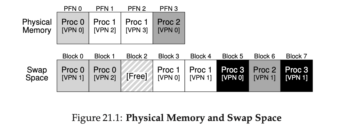
可以在磁盘上分配一块空间用于用于物理页的移入和移出,这称为swap space,当然我们会假设OS以页为单位对swap space读取/写入
示例,假设一个 4 页的物理内存和一个 8 页的交换空间。3 个进程(进程 0、进程 1 和进程 2)主动共享物理内存。但 3 个中的每一个, 都只有一部分有效页在内存中,剩下的在硬盘的交换空间中。第 4 个进程(进程 3)的所有页都被交换到硬盘上,很明显它目前没有运行。有一块交换空间是空闲的。可以看出,使用交换空间让系统假装内存比实际物理内存更大:
The page fault
页错误实际上不算错误,页错误意思是找到的页不在物理内存中,需要从磁盘中换出来,但这个访问本身对用户来说是合法的。 Anyway,页错误的处理流程是:
1 | PFN = FindFreePhysicalPage() |
内核虚拟内存空间
内核虚拟空间是每个用户地址空间的一部分
可以把一部分页表放在内核的虚拟内存中,不会随着context switch而刷新,这样就提升了速度,也减少了用户空间的内存压力
- 放在内核虚拟空间的页表不会被切换,这也意味着其寄存器(基址/界限寄存器)不会被刷新
Question
Use the following information to answer the questions below.
- The base page size is 4KiB.
- Each PTE is 32 bits.
- There are 4 levels in the page table.
- Every level (chunk) of the page table is the same size as the base page size (like in rv32, rv64, and x86).
Bits per index
The number of bits to index each level of the page table: 10.
Solution:
Since the page size is 4KiB, each PTE is 4B (32 bits), there are 4KiB / 4B = 2^10 PTEs in total. So in each level we have 2^10 PTEs to index. As a result, the number of bits to index each level of the page table = 10.
Number of levels
What is the size of the virtual address space. Give your answer in tebibytes (TiB): 4096.
Solution:
Since the page size is 4KiB, the offset takes 12 bits in virtual address. Since there are 4 levels and each level takes 10 bits to index. It takes 4 * 10 = 40 bits to index PTEs. As a result, the total length of virrual address is 12 + 40 = 54, referring to 2^12 = 4096 TiB.