Data Hazards in Pipelined Design
Sources:
- UWashington: CSE378, Lecture11
- UWashington: CSE378, Lecture12
Note: the assembly code in this article can be MIPS or RISCV. This shouldn't be consufusing since the only big difference between them is that MIPS add a $ before the name of each register:
1 | # MIPS: |
Hazards
Hazard is a dependency that causes the pipelines to stall.
Data dependency: Dependency between two instructions occurs when source of a younger instruction is the destination of an older instruction.
- Solution: Forwarding the value from the older instruction to the younger instruction can hide or help thehazard.
Control dependency: Dependency caused by waiting for the decision and target address of the branch instruction.
Solution: Branch prediction.
In the five-stage pipeline model used in basic CPU architecture, control hazards (also known as branch hazards) become apparent in the Decode (ID) stage. This is when the processor decodes the instruction and realizes that it is a branch instruction, which could potentially alter the control flow based on its condition.
However, the decision to stall the pipeline due to a control hazard typically occurs after the branch condition is evaluated, which happens in the Execute (EX) stage for most simple pipelines. It's in the EX stage that the processor can determine whether the branch will be taken or not and what the target address of the branch will be if it is taken.
Structure dependency: Dependency caused by multiple instructions having conflicts in resources, such as the usage of a memory access port for both load and store instructions.
Data hazards
A data hazard arises if one instruction needs data that isn't ready yet.
- Below, the AND and OR both need to read register $2.
- But $2 isn't updated by SUB until the fifth clock cycle.
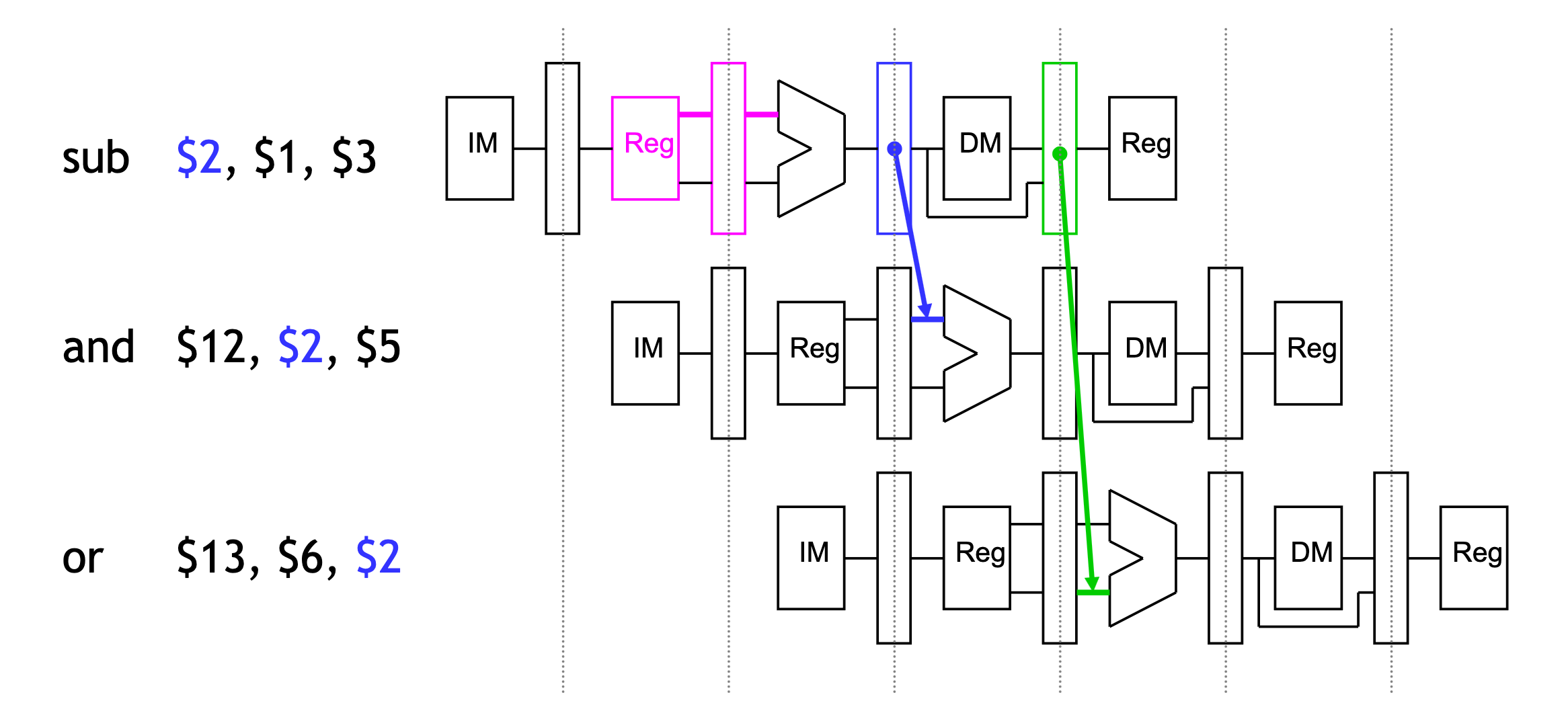
Dependency arrows (explained later) that point backwards indicate data hazards:
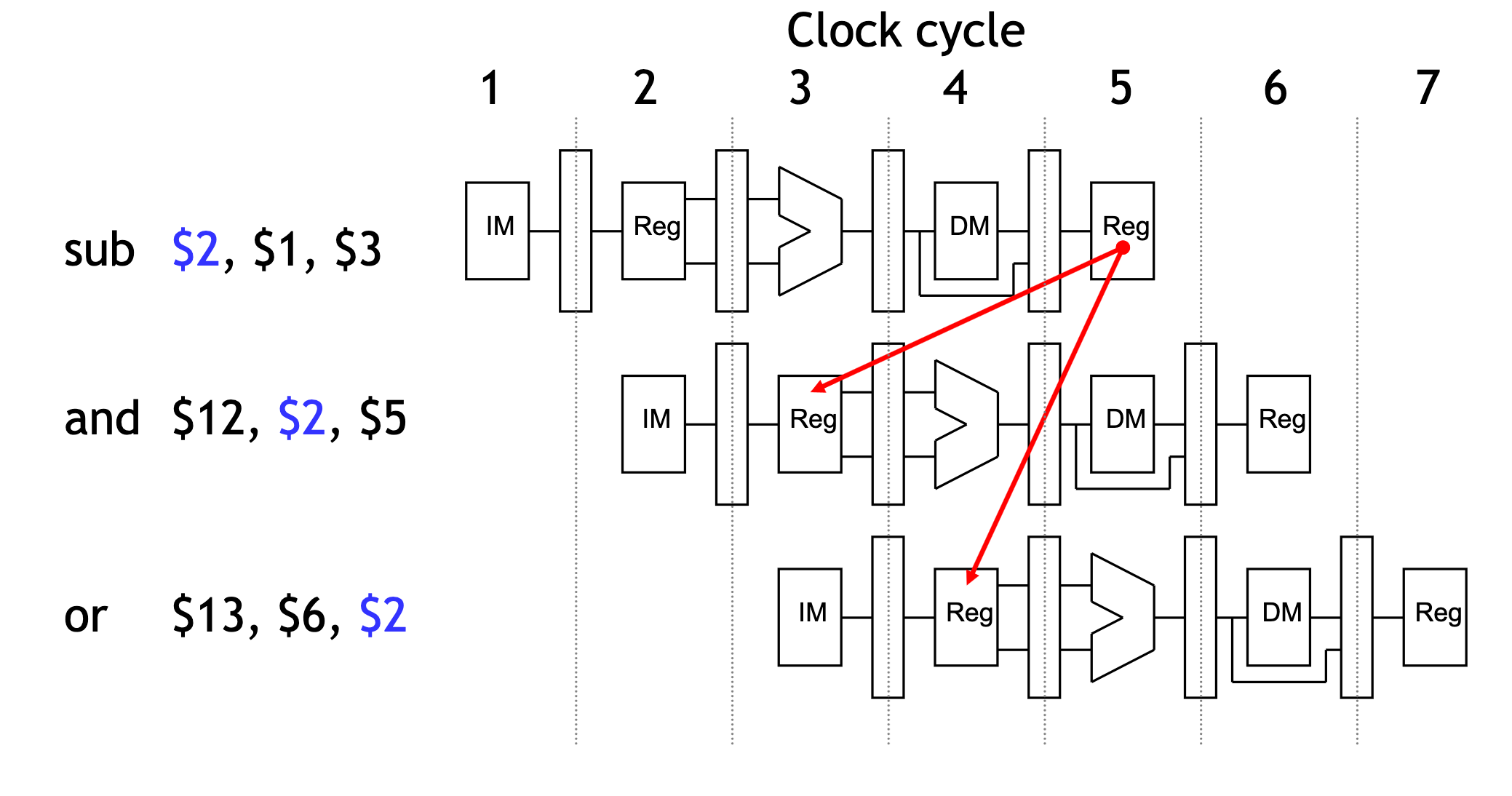
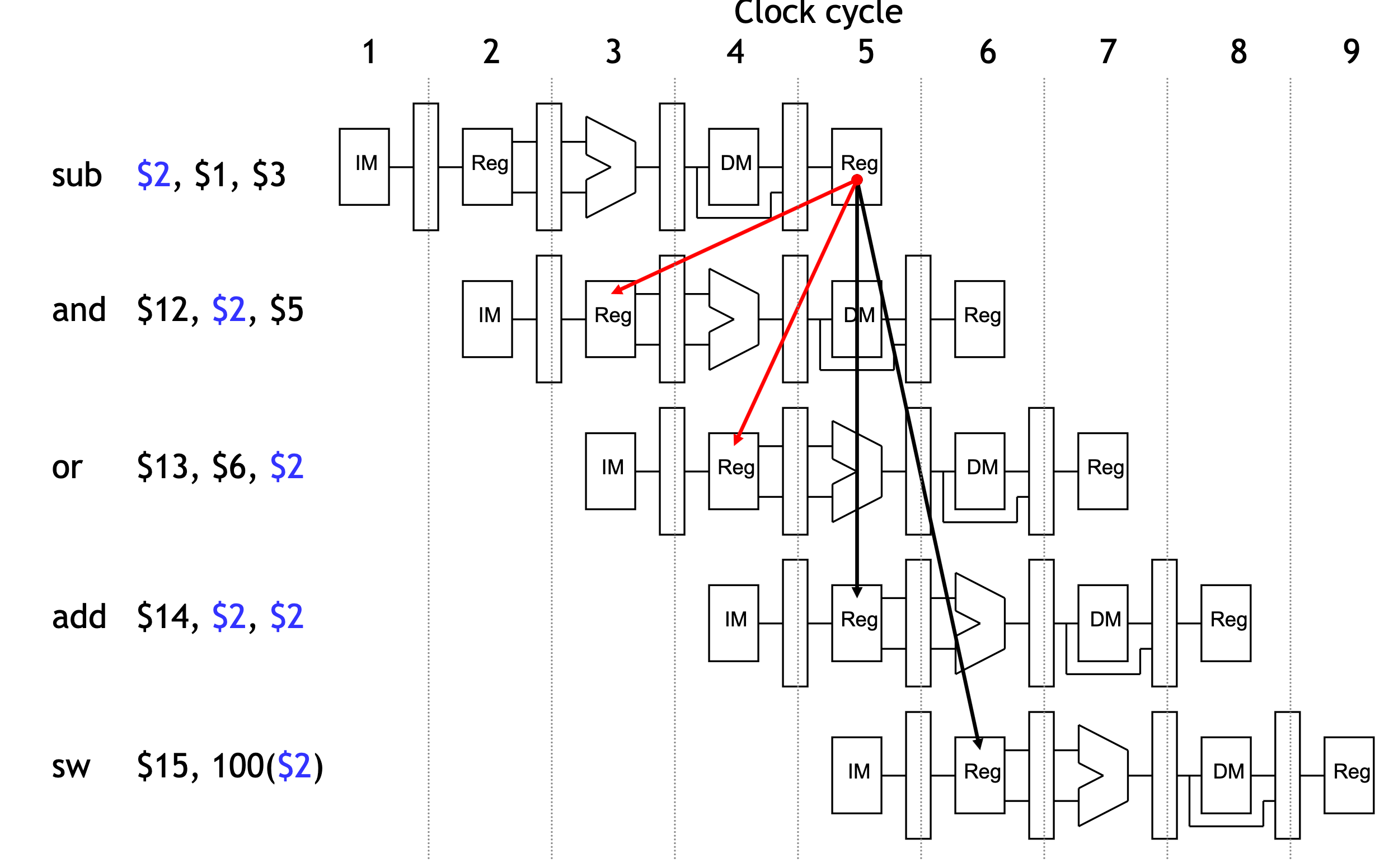
An example of data hazard
The SUB instruction does not write to register $2 (remember that in ID stage we need to read the data in register $2 from register file) until clock cycle 5. This causes two data hazards in our current pipelined datapath.
- The AND reads register $2 in cycle 3. Since SUB hasn’t modified the register yet, this will be the old value of $2, not the new one.
- Similarly, the OR instruction uses register $2 in cycle 4, again before it’s actually updated by SUB.
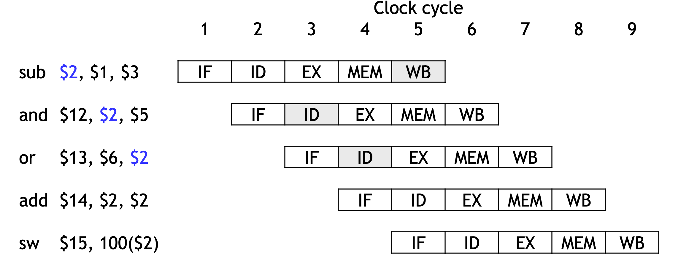
Things that are OK
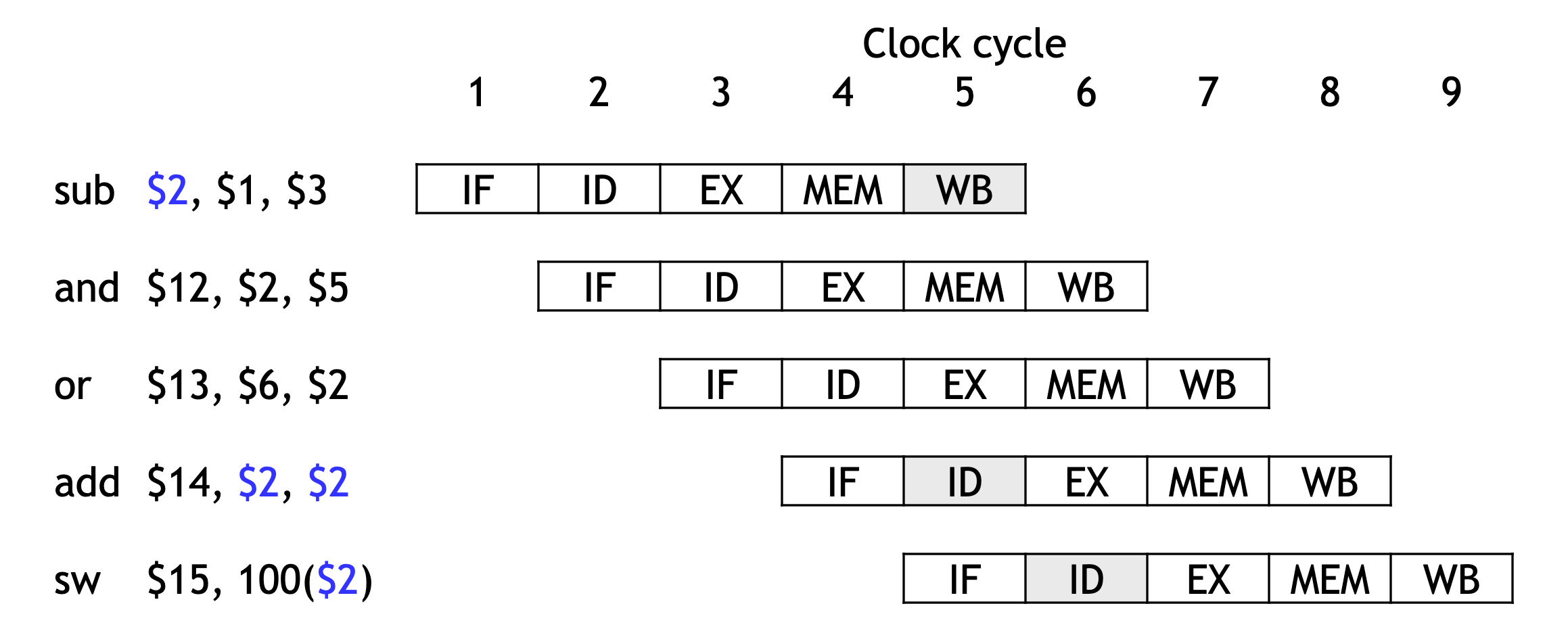
The ADD instruction is okay, because of the register file design. Remember we have regulated that writes occur in the first half of the cycle, reads occur in the second half, so ADD can read from register $2 in the second half of cycle 5.
The SW is no problem at all, since it reads $2 after the SUB finishes.
Dependency arrows
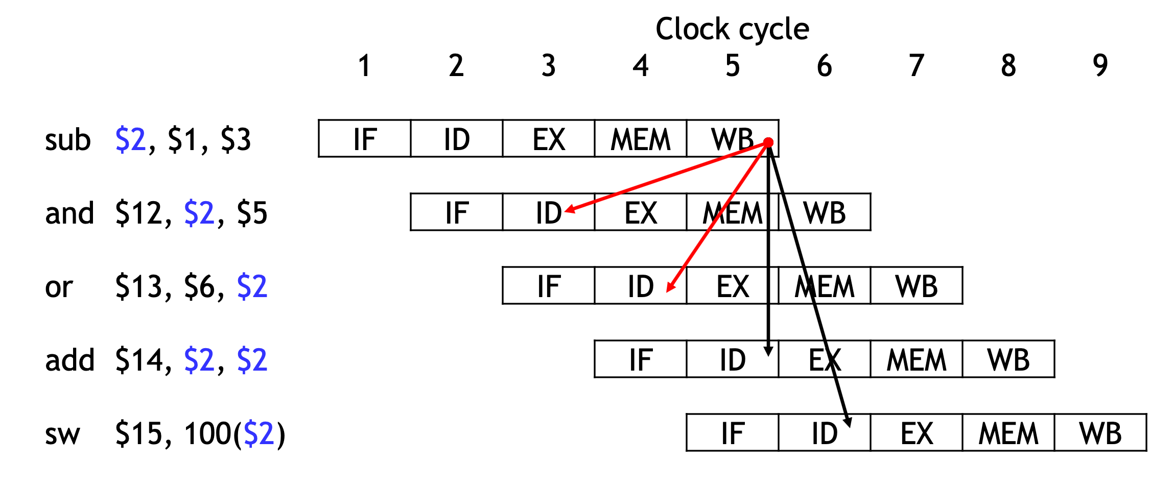
Arrows indicate the flow of data between instructions.
- The tails of the arrows show when register $2 is written.
- The heads of the arrows show when $2 is read.
Any arrow that points backwards in time represents a data hazard in our basic pipelined datapath. Here, hazards exist between instructions 1 & 2 and 1 & 3.
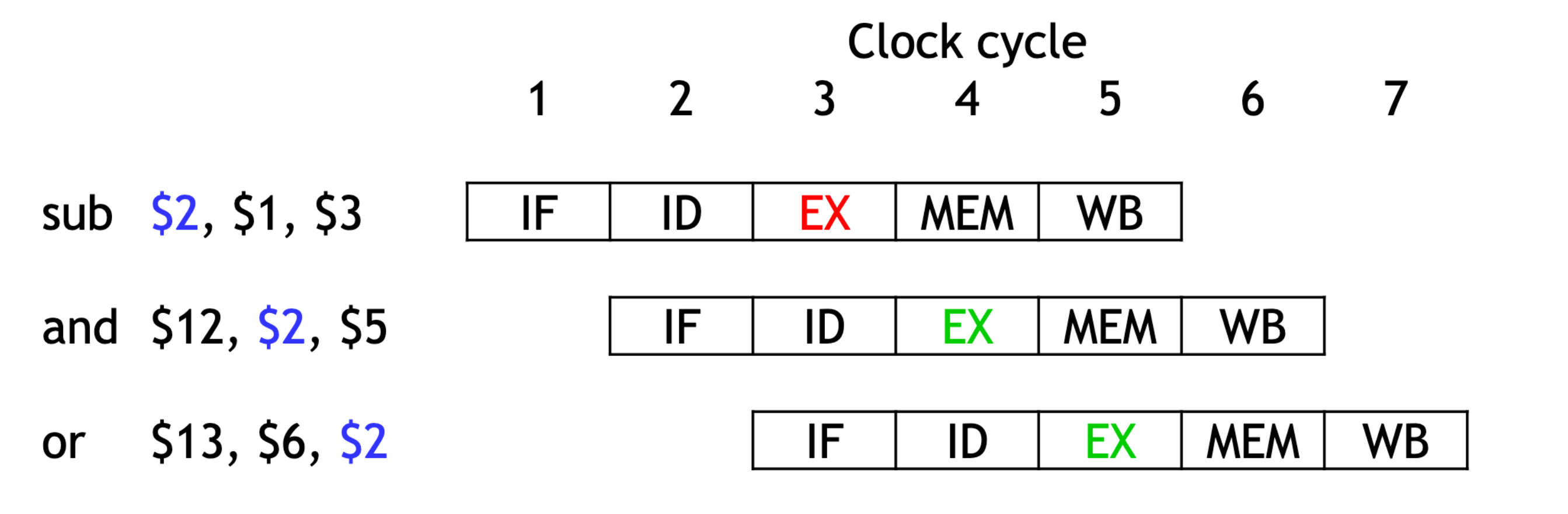
A fancier pipeline diagram:
How to solve it?
We have to eliminate the hazards, so the AND and OR instructions in our example will use the correct value for register $2.
Let’s look at when the data is actually produced and consumed.
- The SUB instruction produces its result in its EX stage, during cycle 3 in the diagram below.
- The AND and OR need the new value of $2 in their EX stages, during clock cycles 4-5 here.
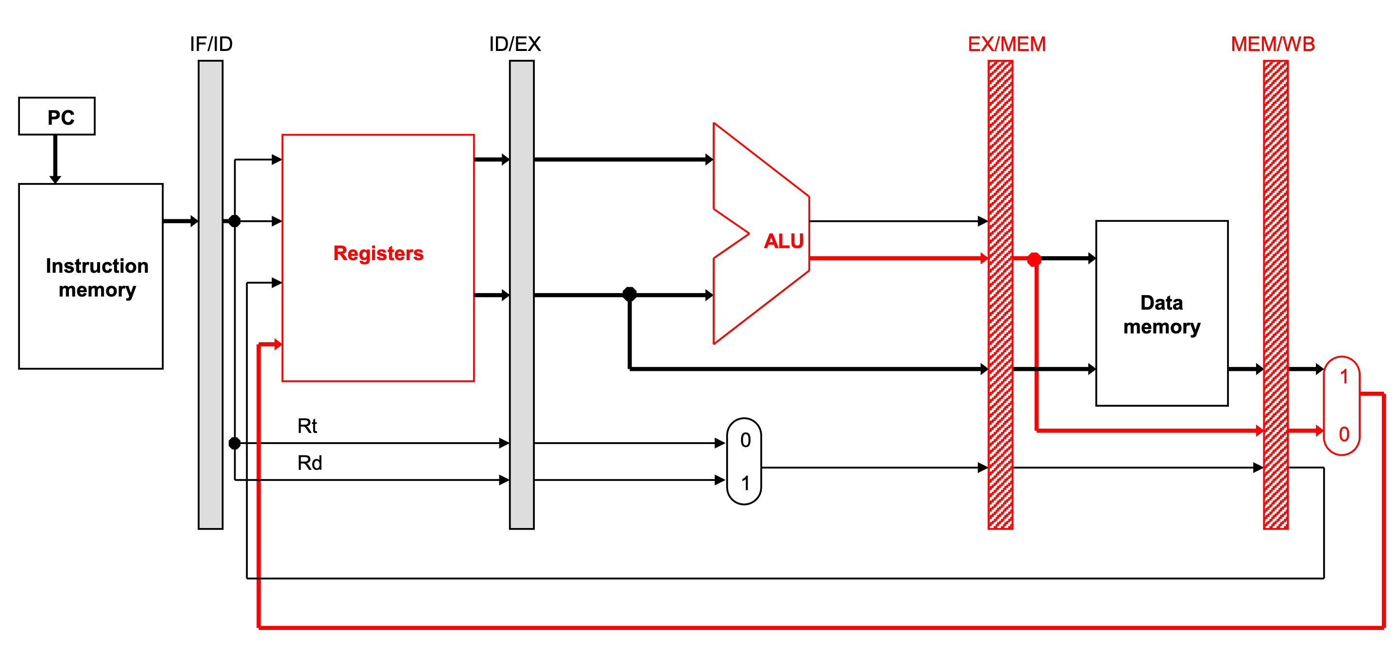
The ALU result generated in the EX stage is normally passed through the pipeline registers to the MEM and WB stages, before it is finally written to the register file.
This is an abridged diagram of our pipelined datapath.
In next section we'll use forwarding technique to solve this kind of data hazard.
Forwarding data from the pipeline registers
Forwarding allows other instructions to read ALU results directly from the pipeline registers, without going through the register file.
Forwarding can only solve data hazards involving arithmetic instructions.
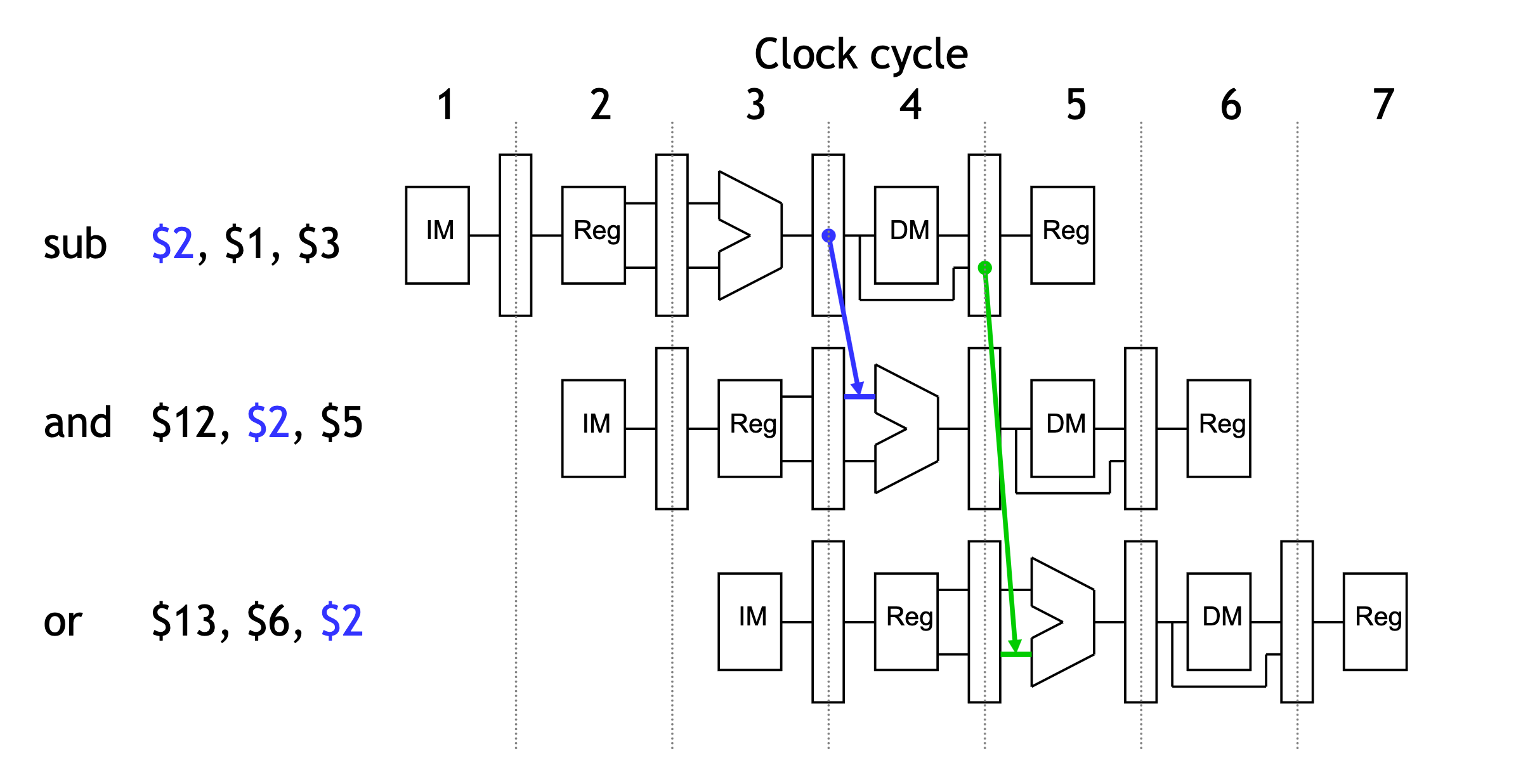
In previous example, the actual result $1 - $3 is computed in clock cycle 3 , before it's needed in cycles 4 and 5. Essentially, we need to pass the ALU output from SUB directly to the AND and OR instructions, without going through the register file.
Since the pipeline registers already contain the ALU result, we could just forward that value to subsequent instructions, to prevent data hazards.
- In clock cycle 4, the AND instruction can get the value
$1 - $3from the EX/MEM pipeline register being used by SUB. - Then in cycle 5 , the OR can get that same result from the MEM/WB pipeline register being used by SUB.
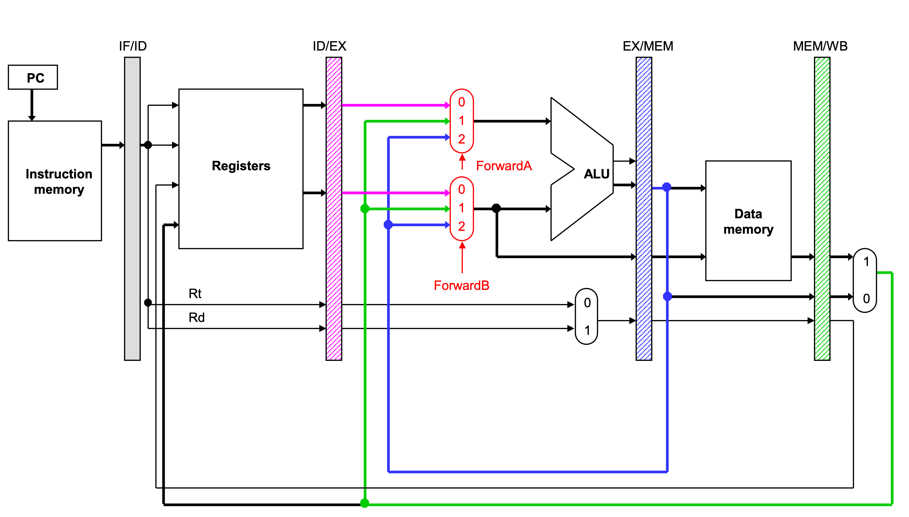
Outline of the hareware implementation for forwarding
A forwarding unit selects the correct ALU inputs for the EX stage.
- If there is no hazard, the ALU’s operands will come from the register file, just like before.
- If there is a hazard, the operands will come from either the EX/MEM or MEM/WB pipeline registers instead.
The ALU sources will be selected by two new multiplexers, with control signals named ForwardingA and ForwardingB.
Simplified datapath with forwarding muxes
The implemention details of the forwarding units and the way to detect data hazards are covered in -->this slide.
Stalling
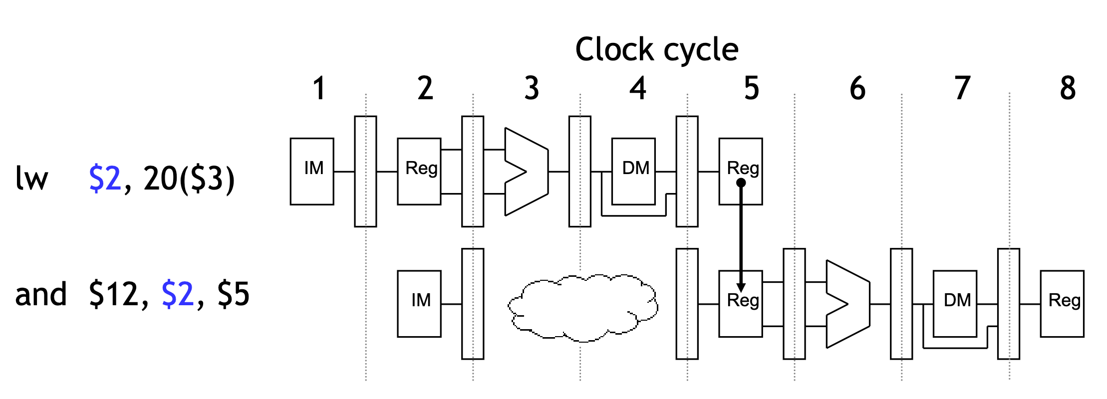
Foewarding can only solve hazards arising from arithmetic instructions. What if the first instruction in the example was LW instead of SUB?
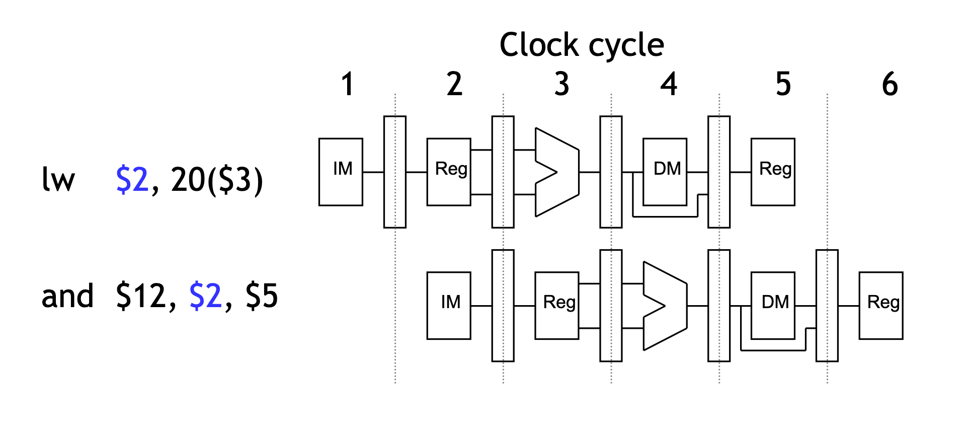
The easiest solution is to stall the pipeline.
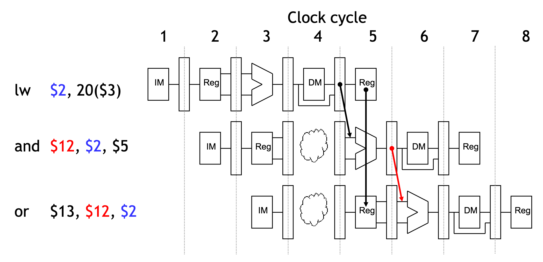
Stalling and forwarding
We could delay the AND instruction by introducing a one-cycle delay into the pipeline, sometimes called a bubble.
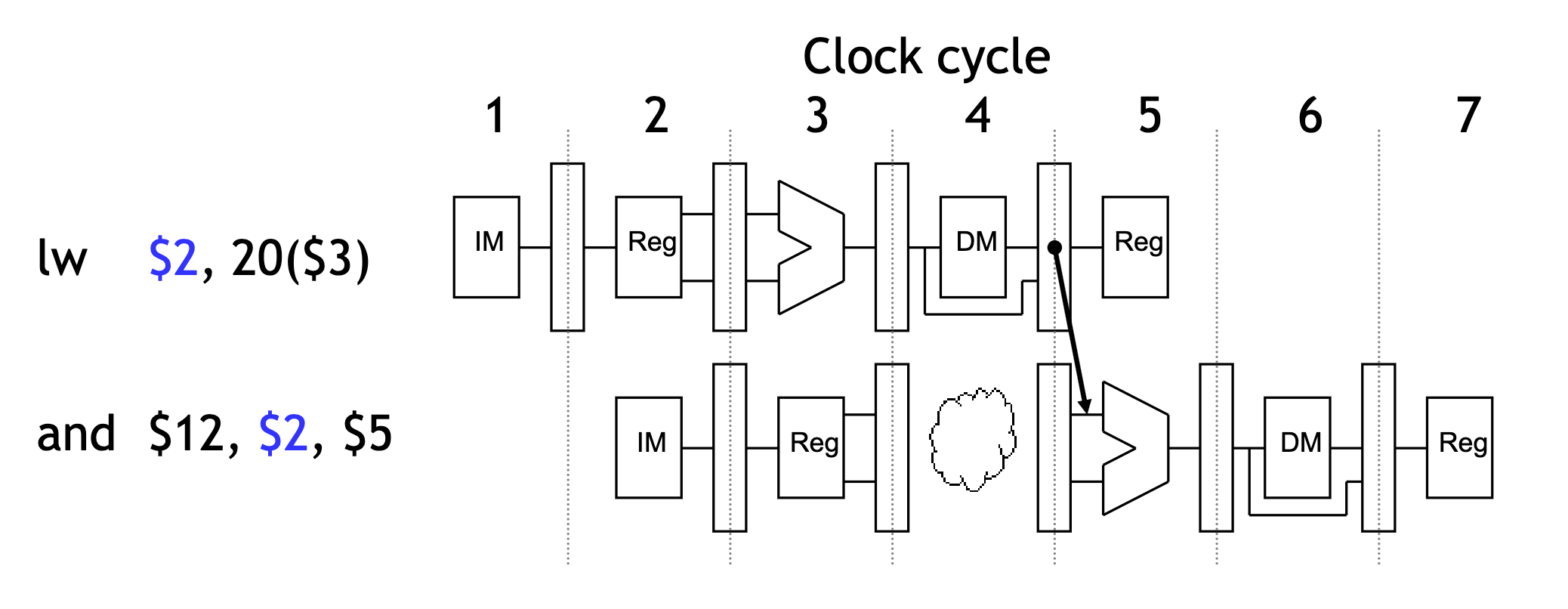
Notice that we’re still using forwarding in cycle 5, to get data from the MEM/WB pipeline register to the ALU.
Just stalling
Without forwarding, we’d have to stall for two cycles to wait for the LW instruction’s writeback stage.
In general, you can always stall to avoid hazards—but dependencies are very common in real code, and stalling often can reduce performance by a significant amount.
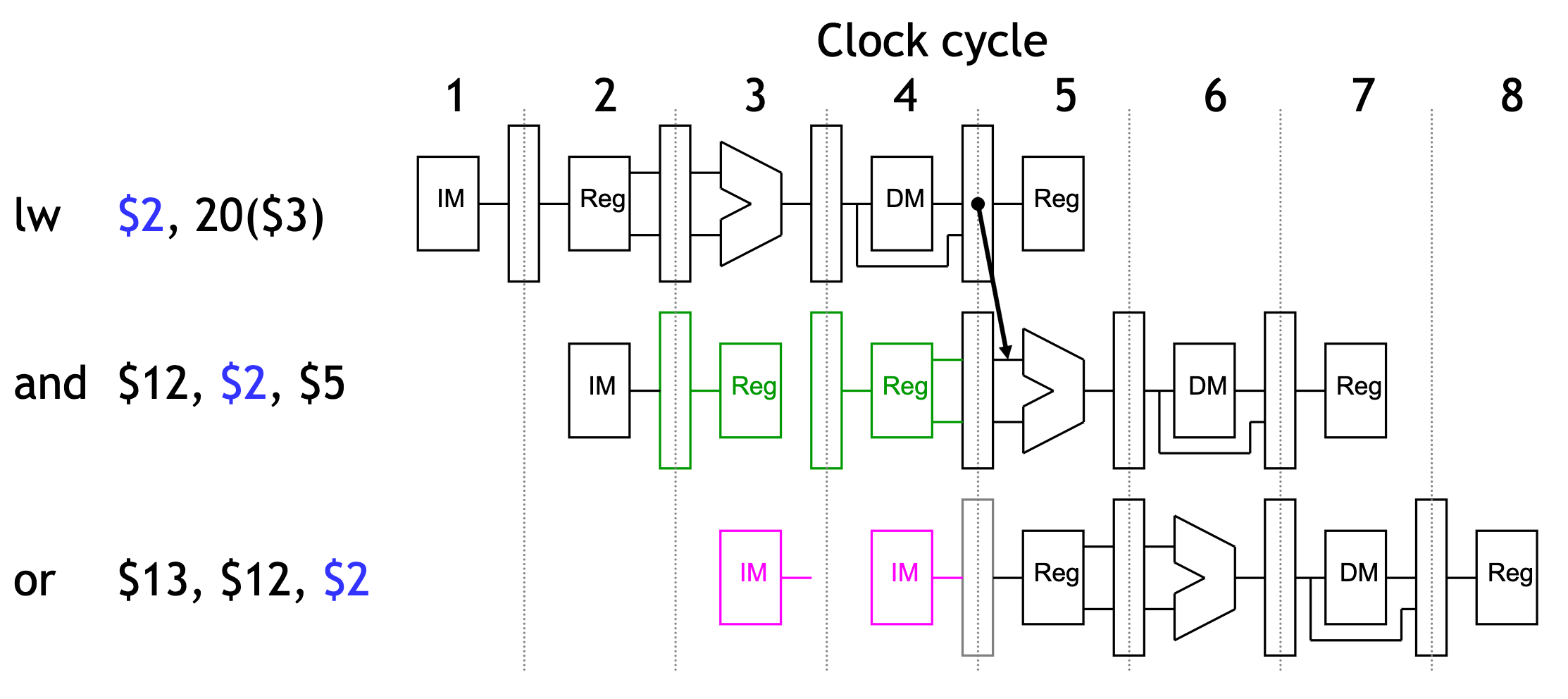
Stalling delays the entire pipeline
If we delay the second instruction, we’ll have to delay the third one too.
- This is necessary to make forwarding work between AND and OR.
- It also prevents problems such as two instructions trying to write to the same register in the same cycle.
During stalling, some hardware may be idling. So we can set the control signals to 0s.
For example, considering the ALU during cycle 4, the data memory in cycle 5, and the register file write in cycle 6, those units aren’t used in those cycles because of the stall, so we can set the EX, MEM and WB control signals to all 0s.
Stall = Nop conversion
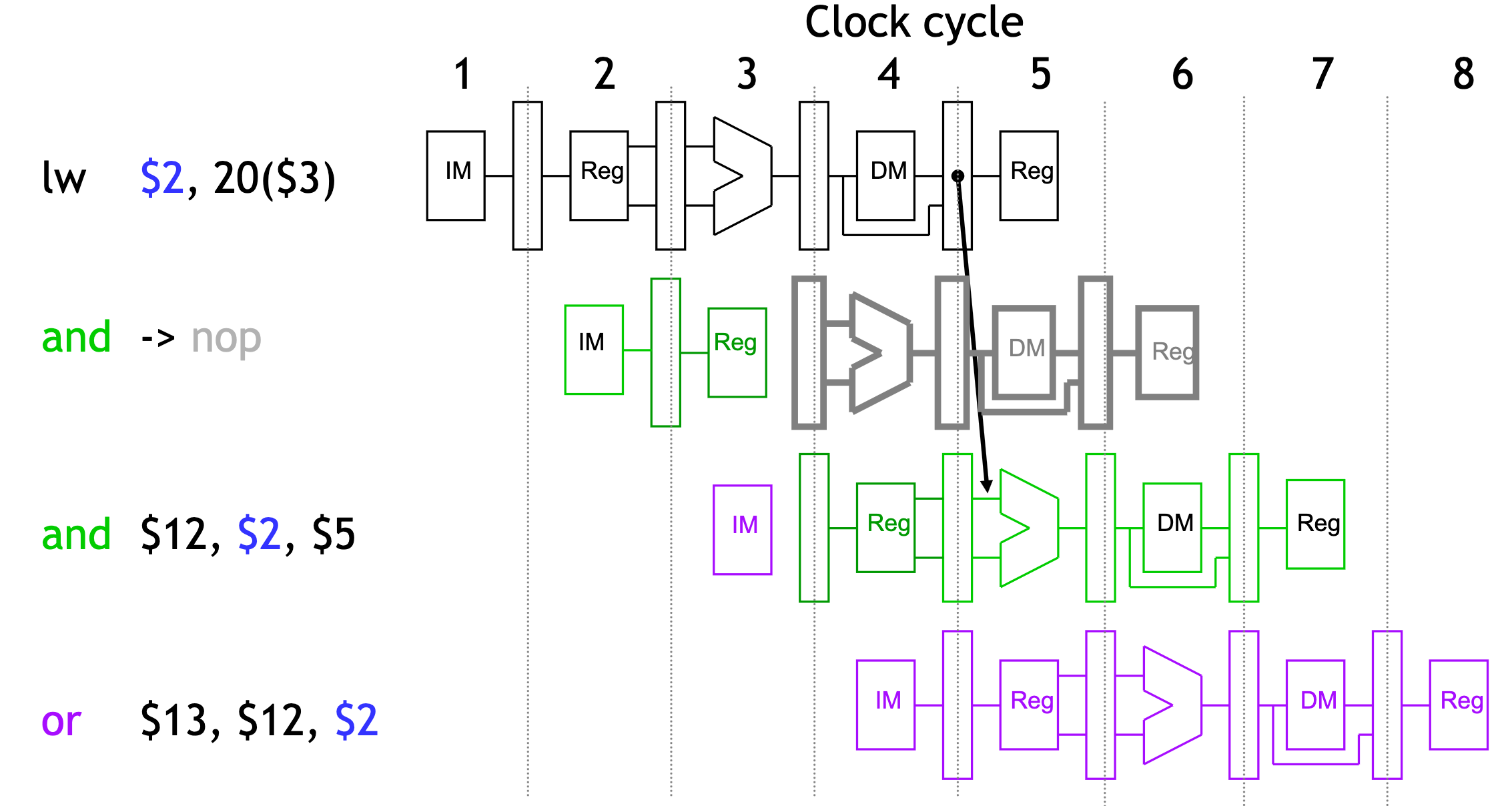
The effect of a load stall is to insert an empty or nop instruction into the pipeline.