Pipelined CPU Design
Sources:
- UWashington: CSE378, Lecture09
- UWashington: CSE378, Lecture10
- John L. Hennessy & David A. Patterson. (2019). Appendix C.1. Computer Architecture: A Quantitative Approach (6th ed.). Elsevier Inc.
- Randal E. Bryant & David R. O’Hallaron. (2016). Chapter 4. Processor Architecture. Computer Systems: A Programmer’s Perspective (3th ed., pp. 387-516). Pearson.

Note: the assembly code in this article can be MIPS or RISCV. This shouldn't be consufusing since the only big difference between them is that MIPS add a $ before the name of each register:
1 | # MIPS: |
What is pipelining ?
Pipelining is an implementation technique whereby multiple instructions are over- lapped in execution.
In a pipelined system, the task to be performed is divided into a series of discrete stages. Each of these stages is called a pipe stage or a pipe segment.
Pipelining increases the processor instruction throughputbut it alsp increases the latency due to overhead in the control of the pipeline.
- Pipelining doesn’t help latency of single load. It'll acturally slightly increase the latency due to the overhead of pipeline registers (explained later).
- Pipelining helps throughput—the number of instructions completed per unit of time—of entire workload.
- Pipeline rate limited by slowest pipeline stage. Since we want to make each state take only one clock cycle, and the clock cycle is bottlenected by the time of the slowest stage.
Single cycle CPU design
In single cycle CPU design, for every instruction, the 5 stages should be executed sequentially.
Since the CPU cycle time can't be changed after the CPU is produced, we must make it larger enough so that every single instruction can be executed in it.
Therefore, the design of the CPU cycle time is limited by the latency of the longest instructions.
Single cycle CPU datapath

Pipelined CPU design
- The cycle time of a pipelined CPU design is the latency of its critical stage (the stage with the longest latency).
- Theoretically the maximum CPI of a single-issue pipelined CPU design is 1.
- However, pipelined CPU design introduces hazards.
5 stages in pipeline
Canonically, we have the following five steps to complete an instruction:
- Fetch the instruction: In this stage, the processor retrieves the next instruction to be executed from memory (or "instruction memory"). The program counter (PC) keeps track of the current instruction address, and after fetching, the PC is updated to point to the next instruction.
- Decode the instruction: figure out what we should do and read the data from the register file. During this stage the bits from the instruction specify which registers need to be read (or written to).
- Execute the instruction: use the arithmetic/logic unit (ALU) to compute a result, the effective address, or direction of the branch.
- Memory: For instructions that involve data memory access (only load and store instructions), this stage is used to read from or write to memory. Load instructions read data from the calculated memory address into a register, while store instructions write data from a register to the calculated memory address.
- Writeback the instruction: (if required) write the result of the instruction to the register file. For arithmetic and logical instructions, this typically involves writing the result into a destination register. For load instructions, the data fetched from memory is written into a destination register.
The processor loops indefinitely, performing these stages. Ideally, each step is finished in one clock cycle.
The execution of single instruction is atomic.
(This five-stage model applies to most RISC ISAs, including RISC-V. For some CISC ISAs, they may use a simpler four-stage model.)
Note that some stages will do nothing for some instructions:

The Classic Five-Stage Pipeline for a RISC Processor
We can pipeline the execution described in the previous section with almost no changes by simply starting a new instruction on each clock cycle.
Figure C.1 is the typical way of pipelining. Although each instruction takes 5 clock cycles to complete, on each clock cycle another instruction is fetched and begins its five-cycle execution. If an instruction is started every clock cycle, the performance will be up to five times that of a processor that is not pipelined.

where
- IF: instruction fetch
- ID: instruction decode
- EX: execution
- MEM: memory access
- WB: write-back
An in-order pipeline in computer architecture refers to a design where instructions are processed in the strict order they appear in the program. This means that each instruction goes through the stages of the pipeline (like fetch, decode, execute, memory access, and write back) in sequence, and each stage must be completed before the next instruction can enter that stage
SIMD Operations: SIMD stands for Single Instruction, Multiple Data. This refers to a method used in parallel computing where a single instruction is applied to multiple data points simultaneously. SIMD units are particularly useful for tasks that involve processing large blocks of data with the same operation, such as in graphics processing, scientific simulations, or operations on arrays/matrices.
Break datapath into 5 stages
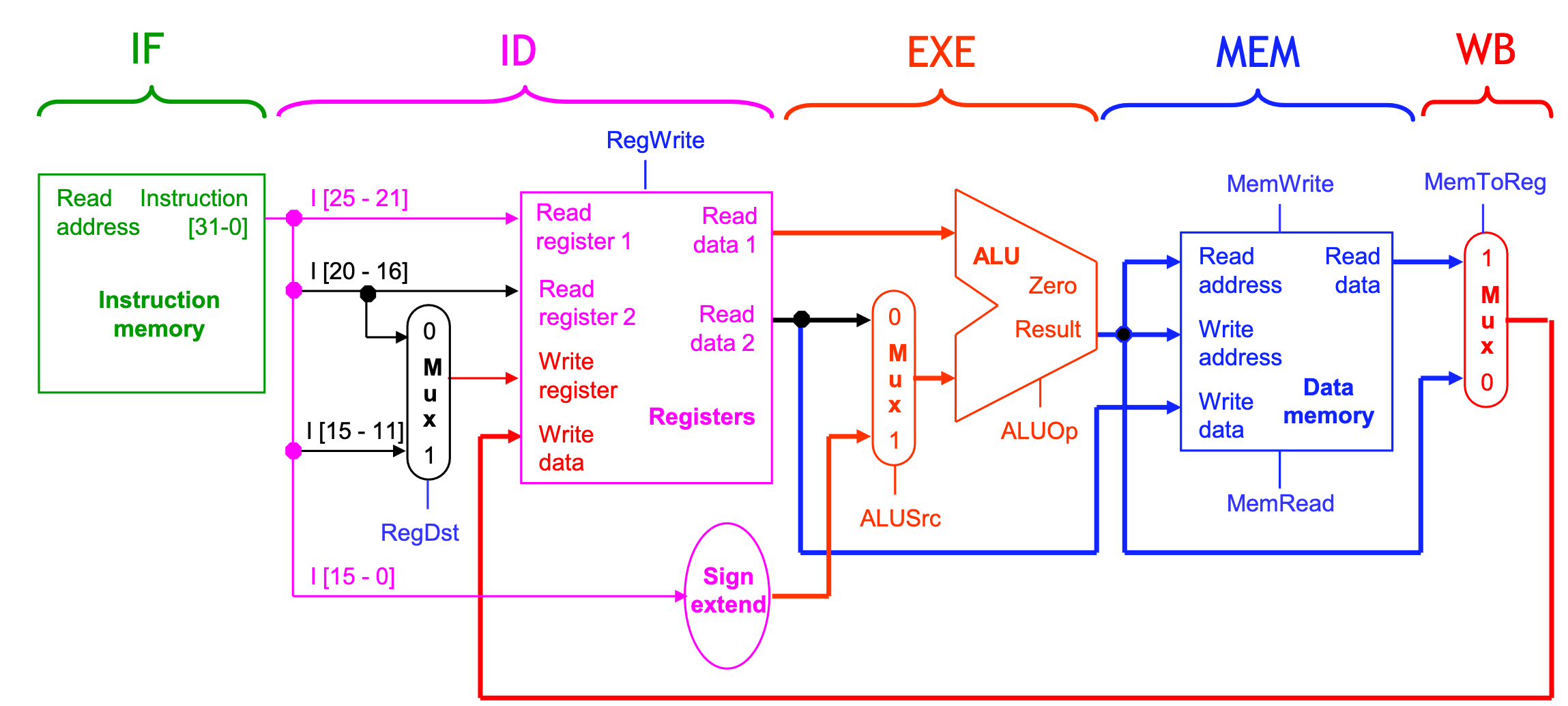
Pipeline terminology

- The pipeline depth is the number of stages—in this case, five.
- In the first four cycles here, the pipeline is filling, since there are unused functional units.
- In cycle 5, the pipeline is full. Five instructions are being executed simultaneously, so all hardware units are in use.
- In cycles 6-9, the pipeline is emptying.
Pipelining Performance

Execution time on ideal pipeline, i.e., each stage takes 1 clock cycle:
time to fill the pipeline + one cycle per instruction
Suppose we have \(N\) instructions, the time costing is:
4 cycles + N cycles
Compare with other implementations: - Single Cycle: \(N\) cycles.
Register file
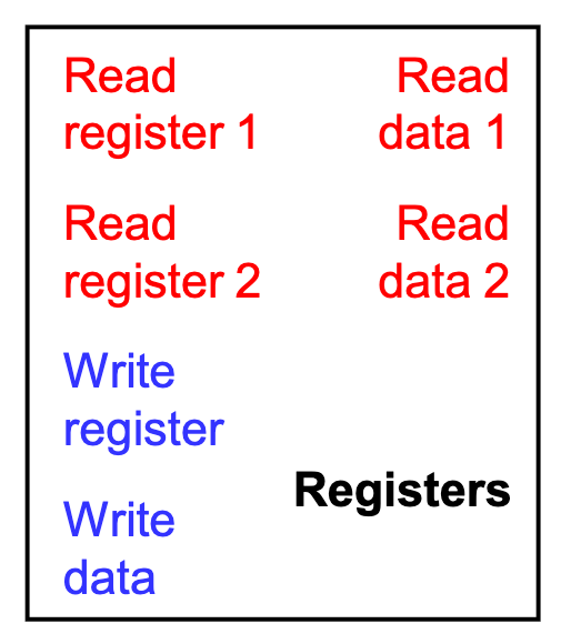
- We need only one register file to support both the ID and WB stages.
- Reads and writes go to separate ports on the register file.
- Writes occur in the first half of the cycle, reads occur in the second half.
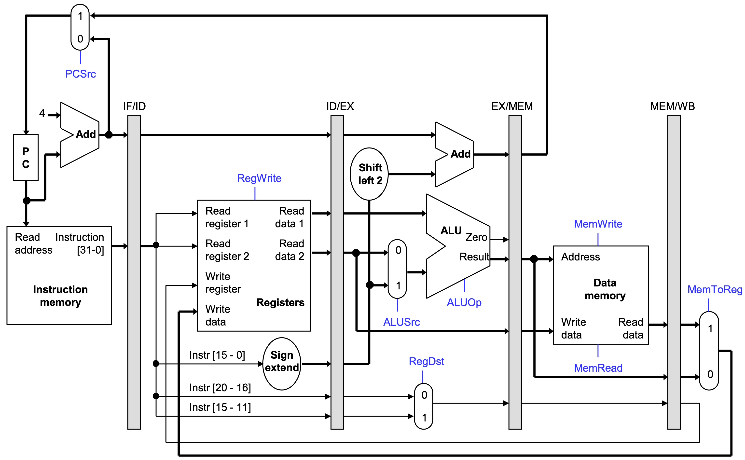
Pipeline registers
We’ll add intermediate registers to our pipelined datapath too.
For simplicity, we’ll draw just one big pipeline register between each stage.
The registers are named for the stages they connect.
1
IF/ID ID/EX EX/MEM MEM/WB
No register is needed after the WB stage, because after WB the instruction is done.
The function of pipeline registers is: propagate data and control values to later stages.
Pipelined datapath
Pipelined control path
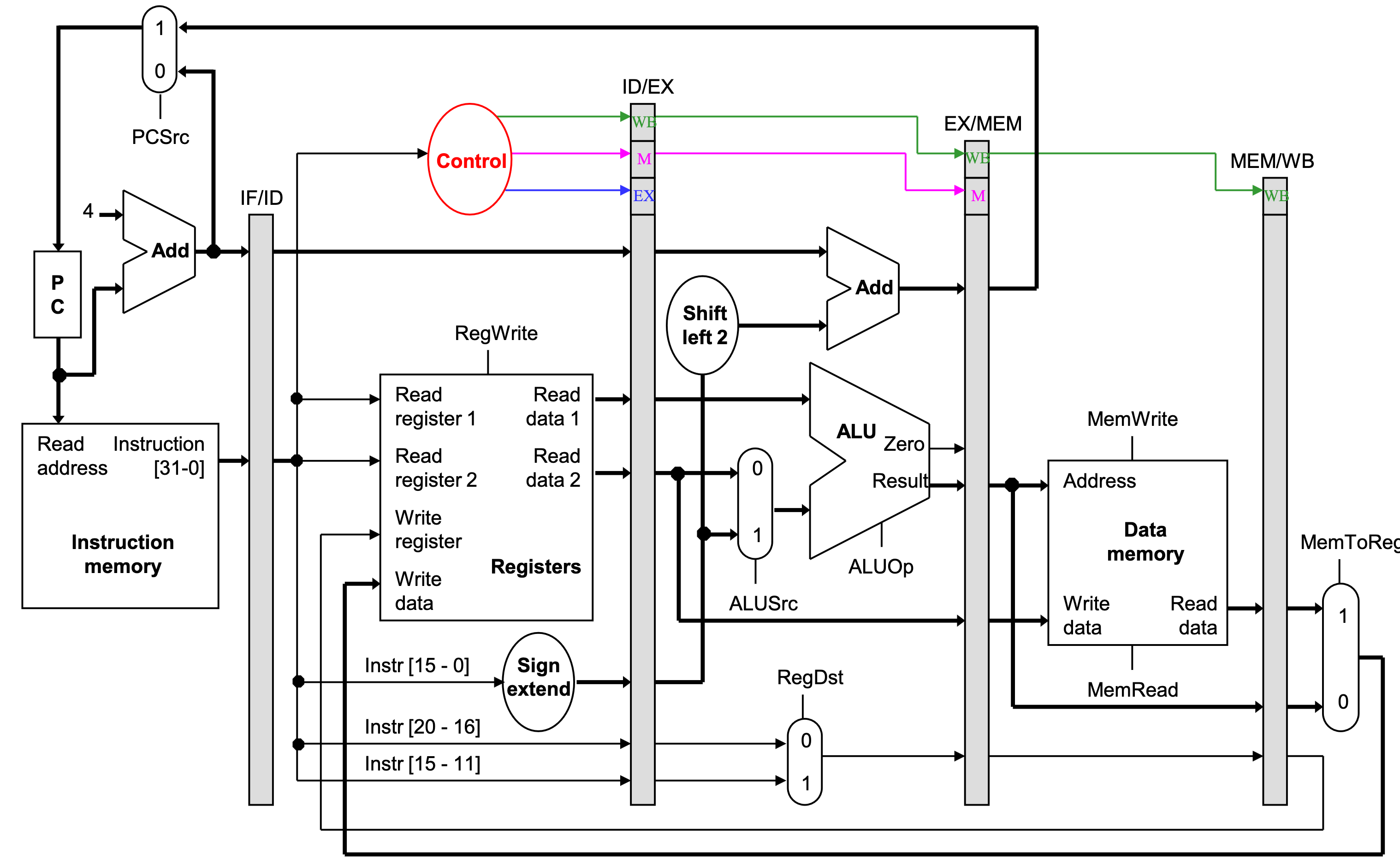
- The control signals are generated in the same way as in the single-cycle processor-after an instruction is fetched, the processor decodes it and produces the appropriate control values.
- But just like before, some of the control signals will not be needed until some later stage and clock cycle. These signals must be propagated through the pipeline until they reach the appropriate stage.
- We can just pass them in the pipeline registers, along with the other data.
- Control signals can be categorized by the pipeline stage that uses them.

Pipelined datapath and control
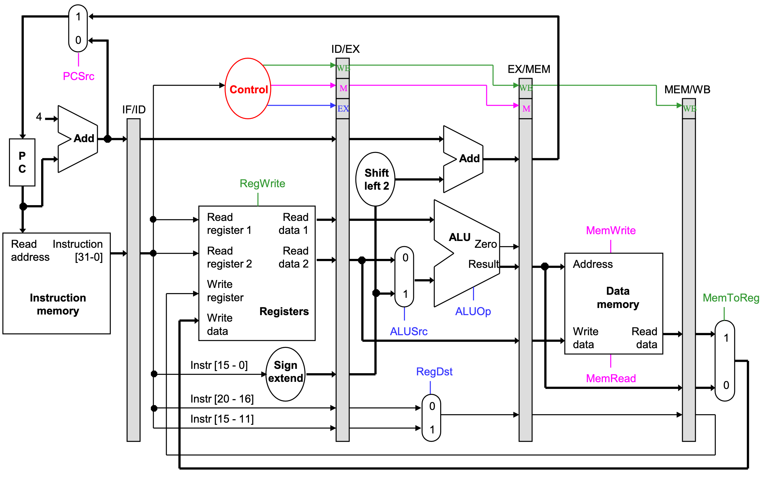
Notes about the diagram:
- The control signals are grouped together in the pipeline registers, just to make the diagram a little clearer.
- Not all of the registers have a write enable signal.
- Because the datapath fetches one instruction per cycle, the PC must also be updated on each clock cycle. Including a write enable for the PC would be redundant.
- Similarly, the pipeline registers are also written on every cycle, so no explicit write signals are needed.
Requirements of pipeline
Note that in pipelined design we have some contraints:
Overlapped instructions can't use the the hardware resources at the same time
Any data values required in later stages must be propagated through the pipeline registers.
The most extreme example is the destination register: The
rdfield of the instruction word, retrieved in the first stage (IF), determines the destination register. But that register isn’t updated until the fifth stage (WB). Thus, therdfield must be passed through all of the pipeline stages, as shown in red on the next slide.Instructions in different stages can't interfere with one another
Notice that we can’t keep a single "instruction register" like we did before in the multicycle datapath, because the pipelined machine needs to fetch a new instruction every clock cycle
Requirement: overlapped instructions can't use the the hardware resources at the same time
In order to use pipeline, one requirement is that the overlap of instructions in the pipeline cannot use the hardware resources at the same time. Fortunately, the simplicity of a RISC instruction set makes resource evaluation relatively easy. Figure C.2 shows a simplified version of a RISC data path drawn in pipeline fashion.

where:
- IM: instruction memory, (more precisely, instruction memory port)
- DM: data memory (more precisely, data memory port)
- CC: clock cycle.
Note: the register file is used in the two stages: one for reading in ID and one for writing in WB.
Requirement: instructions in different stages can't interfere with one another
Another requirement is that instructions in different stages of the pipeline can't interfere with one another.
To achieve this separation, we introduce pipeline registers between successive stages of the pipeline, so that at the end of a clock cycle all the results from a given stage are stored into a register that is used as the input to the next stage on the next clock cycle.
Figure 3 shows the pipeline drawn with these pipeline registers.

Hazards
Dur to these contraints, three kinds of hazards conspire to make pipelining difficult.
- Structural hazards result from not having enough hardware available to execute multiple instructions simultaneously.
- These are avoided by adding more functional units (e.g., more adders or memories) or by redesigning the pipeline stages.
- Data hazards can occur when instructions need to access registers that haven’t been updated yet.
- Hazards from R-type instructions can be avoided with forwarding.
- Loads can result in a “true” hazard, which must stall the pipeline.
- Control hazards arise when the CPU cannot determine which instruction to fetch next.
- We can minimize delays by doing branch tests earlier in the pipeline.
- We can also take a chance and predict the branch direction, to make the most of a bad situation.
Limitations of Pipelining
Diminishing Returns of Deep Pipelining
Figure5 illustrates another limitation of pipelining. In this example, we have divided the computation into six stages, each requiring 50 ps. Inserting a pipeline register between each pair of stages yields a six-stage pipeline. The minimum clock period for this system is 50 + 20 = 70 picoseconds. But the delay due to register updating becomes a limiting factor.
